Elastic Couplings
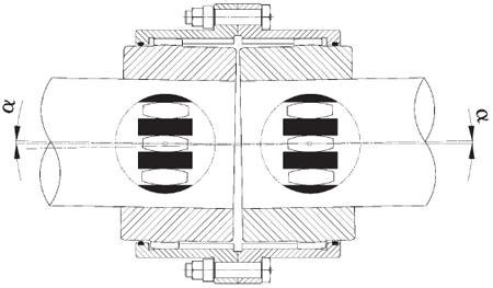
The MT-type threaded coupling is a double joint joint made of steel that allows for deflection along the gears that slide together. The coupling has a torsion-free structure and consists of two parts.
(Parts 2-3-4-5 in Picture-2)
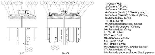
In case of tooth bending; if axial deflection occurs in the shafts, the threaded hubs may vibrate in the flanged outer body. (See Figure-1)
It is impossible for corner pressure to occur even if there is a maximum deviation. Fully machined coupling with gear structure works without noise. Dynamic balancing is recommended at high speeds (if the peripheral speed exceeds 36 m / s and there is no precise balance support).
The teeth are machined on a precision threading machine, guaranteeing the same contact of all teeth.
Threaded couplings are flexible enough to compensate for any deflection and axial play.
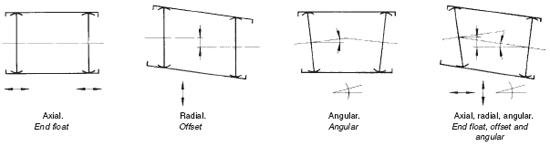
The MT type threaded coupling can be effectively applied for three types of axial deflection.
(See Figure-3)
1. Axial - Shafts are single axis, but shaft axis ends are different from each other.
2. Parallel Offset - The axes of the connected shafts are parallel, but not on the same straight line.
3. Angular - The axes of the shafts intersect with the center point of the coupling, but not on the same straight line.
4. Combined angular offset - The axes of the shafts do not intersect at the center of the coupling and the axes are not parallel.
MT couplings must be periodically filled with grease by the customer. This reduces tooth friction and wear. During the process, the oil is pushed into the tooth by centrifugal force. It is supplied with O-ring to prevent grease leakage.
Threaded couplings are made of CK-45 / CK-55 material as standard. If more compact and higher power coupling is required, HD gears can be used or made with Nitralloy 135 material, such as heat treatment, tempering, induction hardening, and application with cementation steel, etc.
Special threaded couplings up to 6 ° angular deviation
Threaded couplings use tires with NBR material.
These gaskets max. Operates at +75 ° C and min -10 ° C.
Threaded couplings are shipped with rust inhibitors. However, multi-layer epoxy painting can also be done as an alternative protection.
The choice of coupling to be used in drive systems is not only dependent on the force and speed of the drive. The axial deflection and the type of machine on which the coupling is to be used must be considered.
Proper maintenance and lubrication are key to prolonging the life of the coupling.
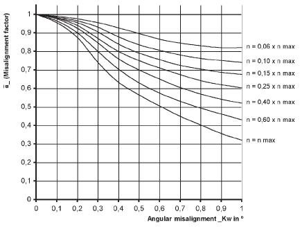
The coupling must always be installed according to the recommended instructions. Correctly aligned coupling of the coupling teeth evenly transfers torque. If there is an angular shaft deflection, the thread pressure is not equal, which reduces the coupling capacity.
Figure 4 shows an example of a decrease in force as the shaft deviations and speed increase.
Due to the sliding of the gears, the coupling generates axial forces under deflection. These forces should be taken into consideration during the design phase of the machine.
Coupling selection:
The minimum values for the selection of MT type threaded couplings are as follows:
- P N : Required or required power (kW) - n : Working speed (r / min) - L : d shaft lengths and diameters (mm) - DBSE or LM : Distance between shaft ends (mm) - K : Service factors (See Figure-5)- F µ : Deviation factor (See Figure-4) - Additional geometric or atmospheric limitations.Calculation:
1) Estimated nominal torque T N (Nm) x Service factor K x F µ deviation factor
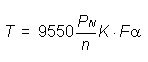
P N = Max. Real power (kW) n = Coupling speed (rpm) K = Service factor F µ = Deviation factor
The nominal torque (Nm) is multiplied by the service factor and the deviation factor. Higher capacity coupling type should be selected. Check whether the maximum torque of the application is below the maximum torque (TP) of the coupling.
2) If the diameters of the drive shafts are larger than the coupling bore diameter, an upper type coupling must be selected.
3) The shaft / hub connection should be checked whether it will transfer torque or longer hub should be preferred if necessary.
4) The listed speeds are maximum speeds for unbalanced couplings. For high speed applications, the coupling must be dynamically balanced and other materials other than carbon must be used.
5) Recommended Service Factors (K):
The resulting dynamic moment has to be transferred, the power transferring by increasing the power will provide instantaneous moment rise by the factor according to the characteristic structure of the equipment. In Figure 5, the service factors basically show the estimated technical combination of the connected equipment.
These factors are obtained through long experience and average practices and are generally guidelines. Correct decision-making should be carried out for working conditions not shown in the table. A factor should be selected as the type of equipment closest to the type of application considered, or it should be selected according to the detailed analysis of the equipment dynamics.
Sample:
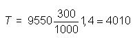
Select a coupling and attach it to the drum conveyor (without balanced load).
Engine power PN = 300 Kw. Drum speed n = 1,000 rpm. Gearbox shaft diameter d1 =Solution:
Service factor K = 1.4
Drum shaft diameter d2 =
The resulting service factor is: