Reducer Glossary
Input Speed (n1-rpm): High speed at which the gear unit operates. If the gear unit and motor are directly connected, the input speed of the gear unit and the motor are the same. For the technical data in the catalogs, the nominal input speed is based on an ambient temperature of 20 ° C.
To use at a higher ambient temperature, the input speed must be reduced.
Output Speed (n-rpm): The output speed is calculated as in the formula shown below .
nc = n1 / i
i = Reduction ratio (Transfer)
Gear transmission efficiency: Efficiency is less than 100% because there is a loss of power due to friction. It refers to the efficiency in this catalog and the gear unit is assumed to be operating at full load .
Output Torque T N (Nm): The load bearing function of the gear unit continuously (without wear) is called torque.
There is a direct correlation between the load carrying function and the life of the gear unit, the operating time of which depends on the frequency of overloading.
Acceleration Torque T i (Nm): The acceleration torque, T i, is the maximum permissible moment and can be transferred to the maximum number of cycles = 1,000 cycles / hour. This also depends on the shape of the load and the permissible acceleration time.
Acceleration torque required in operation, the gear unit nominal value of the acceleration torque T i must be smaller than the skin, or reducer's life is reduced.
Emergency Stop Torque T 2Not (Nm): It is the maximum torque value that the gear unit will carry on the output side depending on the time and number of repetitions. It is accepted that the gear unit can only be loaded 1000 times per hour, this value may vary according to the gear unit manufacturers.
No Load Torque T N1 (Nm): This torque is the value required to overcome internal friction.
Maximum Torque T 2max (Nm.): This is the maximum output torque of the gear unit which is in a static state or is over-periodically processed. It is commonly known as instantaneous maximum load or starting torque load.
Required torque T 2N (Nm): It is determined according to this application and must be equal to and less than the output torque (T N ) of the selected gear unit .
Calculated Torque T c2 (Nm): The torque applicable to the selected gearbox can be found by the formula shown below.
fs = service factor
T c2 = T 2N * fs < T N
Parallel Moment M 2 (Nm): This is the effective value of the output bearing of the axial and radial forces (this is the point at which the internal radial force acts).
We can reach this value with the following formula.
M 2 max = [F 2a max . * y 2 ] + [F 2r max . * ( x 2+ z 2) ] / 1000
Axial Force F 2amax. (N): It is the force parallel to the output shaft when the gearbox is operated. If applied in axial position (y2) parallel to the output shaft, it creates a bending moment. If the axial force exceeds the value in the catalog, the bearing will need additional design to carry this force.
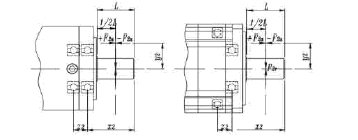
Radial Force F 2r max (N): The force acting vertically on the axial force. In this case, the point of action or moment arm has an axial distance from the shaft side. The radial force produces a bending moment.
Radial load, axial load: Other factors when selecting gearboxes are the radial load and axial loads that occur on the output shaft. The permissible radial load depends on the strength of the shaft and the load capability of the bearing. It is the maximum permissible value in the catalog to apply the force to the weakest point to the midpoint of the output shaft (1/2 L).
If the force acts on the side close to the gearbox from the center point, not from the center point of the output shaft, the gear unit is allowed to carry more axial loads.
Safety factor S: Safety factor; nominal power to motor power.
Service factor fs: The service floor value is the functional performance of the gear unit and relates to the type of load on the gear unit and the daily operating time.
Crimping Ring: Thanks to the locking part of the crimping ring; a portion of the element is connected to the movement-giving side. With a certain force, this clamping apparatus presses the surface to be driven and a gapless joint is obtained.
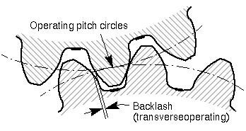
Gear Clearance ('): Maximum deviation between output and input shafts. In order to overcome the internal friction, the gap is measured after fixing the input shaft and a torque (by means of the device) is loaded onto the output shaft with the specified test torque.
Synchronization Error: Synchronization error is the speed change resulting from the measurement of the input and output speed in a circle of the output shaft. This error caused by miniature angular deviations and fluctuations is due to the tolerance of the gear manufacturing.
Reduction (Conversion) Ratio i: This is the mathematical ratio between the input speed and the output speed of the gear unit . Moment and inertia values change with speed change.
Noise level (dB): Low noise level (db) is one of the most important factors in environmental pollution and health. Motor speed and power, gearbox size and ratio directly affect this noise level. In general: A higher speed means a higher noise level; but a high rate means a low noise level.
Noise level as input speed 3000 dv / min and
Average Gear Life (h): Continuous operation of the gear unit is calculated based on nominal power and input speed.
Speed n (dv / min): Two speed values should be taken into consideration when selecting the gearbox . Maximum input speed and nominal input speed. The maximum permissible speed n max must not be exceeded, as the cycle is part of the process . The nominal input speed n max must never exceed the continuous operation. The gear unit operating temperature limits are equal to the sum of these values, so it should not exceed 90 ° C. More precisely, if the ambient temperature is high, the input speed must be reduced.
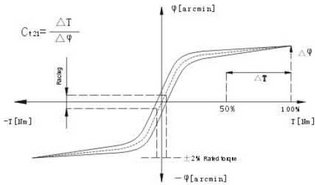
Delay Curve: The test of the delay is performed to determine the torsion capability of the gear unit. Another name for this measured value is the space curve. By preventing rotation of the input shaft, torque is applied to the output gear, this movement continues to be applied step by step and the nominal torque is exceeded. In this case, the oscillation of the output side is calculated by means of a curve.
Inertia Moment J (Kgcm 2 ): Inertia moment J is a measure of the value that indicates the desire of the motion element to maintain its position when rotating or stopping.
Inertia Proportion : Inertia ratio is the ratio of the inertia of the loaded side (application side) to the inertia of the inertia transmission systems (motor and gear side) . It is an important parameter in determining the controllability of an application. Precise control of this dynamic process depends on this rate. For this, the inertia ratio value is max. 5..10. The conversion ratio factor in the gear unit can be reduced by 1 / i 2 .
Inertia Proportion Factor = (J inertia of load * 1 / i ² ) / (J motor + Gearbox )
Minute ( '): We define in minutes divided into 60 angular degrees a. (1 ° = 60 min.) Words, if the gap is determined at 1 minute the output angular deviation 1/60 °.
Example: Gear unit with an angular clearance of 5 min.


